Production, Startup, Commissioning and Maintenance of Control Panel by a Control System Integrator (Complete Compilation)
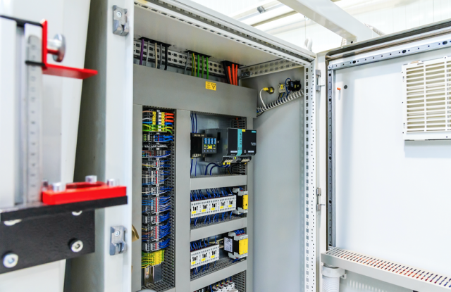
Control Panel Layout and Mounting of Electronic Components
In building the subpanel, it is best to secure the components from the front side. This will make it easier to replace any failed device or component in the future. We can also make installation and maintenance easier by using terminal blocks mounted to the subpanel that will connect to all external devices. This will allow the installing electrician to quickly dress and terminate the field wires. Another terminating method that has added benefits is to design our control panel using mating connectors also known as connector plugs. This terminating method enables field wiring to be simply plugged into connectors mounted on the panel.
Electronic instrumentation is typically installed inside an enclosure with other devices. Therefore, the installation of the instrumentation must take into consideration that the panel layout accommodates all necessary components. In addition to the panel layout, the following should be considered.
Electronic instrumentation can be affected by interference from other electronic devices or EMI (Electromagnetic Interference). This interference causes static that may interrupt communications or signals from other devices. Use these guidelines to prevent any possibility of interference with your equipment:
- Environmental specifications that cover the operating temperature, humidity, vibration, noise immunity, etc.
- Power requirements are specific to each piece of equipment. When installing instrumentation always make sure to follow the manufacturer's power requirement guidelines for your specific piece of equipment.
- Use components with Agency Approvals such as UL (Underwriter Laboratories), CE (Conformitè Europëenne), etc.
- Make enclosure selections based on component dimensions, recommended mounting clearances, heat dissipation, and EMI.
If installing a PLC (Programmable Logic Controller) base or chassis which consists mainly of mounting, bonding, and grounding, it is very critical to the proper operation of the PLC and its related devices and components to closely follow the manufacturer's recommendations. There are many causes of a PLC experiencing "noise" problems when the problem is found to be that the base wasn't grounded to the subpanel.
Wiring Recommendations
The following guidelines provide general information on how to wire most control panel electronic components. Always refer to the installation manual of the electronic components to know specific requirements.
- Choose a wire depending on the application requirements. The selection of wire is dependent on voltage, temperature, and type. Each terminal connection is recommended to accept 16 AWG or two 18 AWG (American Wire Gauge) size wires.
- Splicing of wires should not be done to attain a needed length. Always use a continuous length of wire. Never splice wires to attain a needed length.
- Use the shortest possible wire length.
- Use a good wire management system for routing of wire to minimize the use of wire ties.
- Avoid running control wires near high-energy wiring.
- Avoid running input wiring close to output wiring where possible.
- To minimize voltage drops when wires must run a long distance, consider using multiple wires for the return line.
- Avoid running DC wiring in close proximity to AC wiring where possible.
- Avoid creating sharp bends in the wires.
- Install a powerline filter to reduce power surges and EMI/RFI noise.

Grounding Requirements
Electronic instrumentation such as PLCs and field I/O are typically surrounded by various types of electronic devices and wires. These electronic devices may include power supplies, input/output signals from other instrumentation, and even devices that are near the instrumentation enclosure. All these may present a risk of Electromagnetic Interference (EMI) or transient interference. This type of interference may cause erratic operation of components and cause failures.
In addition to device interference, automation equipment and devices could be damaged by powerful line surges. These line surges may come from common voltage fluctuations from a power supply, lightning, or unintentional contact with a high voltage line. A power surge will cause a temporary failure, fuse burn-up, or could cause serious damage to the equipment. Grounding provides a low impedance path that limits these voltages and stabilizes interference. Grounding is a must to protect your automation equipment and devices from serious damage, failures, and even potential risk to users. Grounding is the foundation of achieving a reliable power distribution system. During the panel and control system build, it is important that a reliable grounding system be implemented. Poor grounding or improper or defective wiring may be the cause of most problems affecting power quality.
- Mounting: refers to the actual physical installation of each device, instrument, or component to either the subpanel or other connected equipment.
- Bonding: refers to the joining of metallic parts of a chassis such as; frames, shields, assemblies, and enclosures. Joining or bonding these components properly reduce the interference from EMI and ground noise.
- Grounding: refers to a connection to a grounding conductor to provide overload and interference protection.
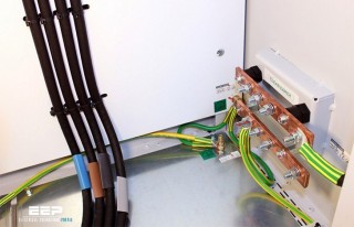
Wire all grounds to the incoming ground lug either directly or with a wire to the other ground bus bars. Add a main ground lug and/or a ground bus bar for each grounded power supply. A number of busbars can be utilized but should all be wired together and then to the incoming ground lug to at least 1 point if not two (2). This is in addition to the ground established through the panel. Use 2 ground wires from opposite ends of the bus or chain of ground bars if the ground is isolated. Wire the ground on all doors and subpanels and the cabinet itself to a ground bar terminated at the main ground lug. Wire all equipment and chassis grounds to the ground bar(s) which is terminated at the main ground lug. For additional details on grounding and bonding see the Grounding and Bonding post dedicated to just this subject.
Use of Shielded Cables
Shielded cables are electrical cables that contain insulating conductors encased in a standard conductive layer. They are used to reduce interference from electrical noise. Some instrumentation requires the use of shielded cables for specific connections as electromagnetic interference can reduce their performance. When installing instrumentation, it should be verified whether any connection requires a shielded cable. If the product being installed requires shielded cables, the grounding specifications provided by the manufacturer's manual must be followed. Failure to use the shielded cable will result in faulty readings or signals from the instrumentation. Improper installation of shielded cables may cause a ground loop that will cause failure on a processor or would allow noise into the logic circuit. The cable must be grounded at one end. This eliminates the potential for noise-inducing ground loops. The cable selected should have sufficient shielding for the application's needs. In moderately noisy environments, a foil alone may provide adequate protection. In noisier environments, consider braids or foil-braid combinations. Use an earth ground wherever possible and check the connection between the ground point and the equipment. Eliminating noise depends on a low resistance path to the ground therefore it is important to ensure that the equipment the cable is connected is properly grounded.
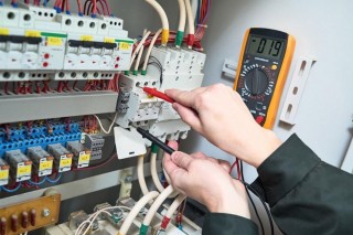
I/O and Communication Testing
The I/O testing is a process where using a PC connected to the PLC the status of each point being tested is viewed and outputs are simulated by physically applying a signal to inputs and monitoring outputs with the use of an indicator on discrete outputs and a meter on analog outputs. The I/O checkout assures that point-to-point wiring between I/O module terminals and the field wiring terminal are done correctly. To start I/O testing a list is created from the I/O list used for designing PLC or HMI applications. Each I/O point is included on the list with details of what criteria is being tested. The communication between devices connected by Ethernet and/or fiber is also checked during this testing.
Automated Control System Startup and Commissioning
Startup and commissioning of the automated control system will occur in stages. The startup of an automated control system begins once supplied control system enclosure is installed, field wiring is terminated, and testing for each individual system is completed. As each component is brought online for automated control in stages, the automation system is used for a remote startup of equipment as this is how operators will operate the system on daily basis. As a starting point, it is best to isolate the various sections of control system power wiring by removing the fuses and/or opening circuit breakers. The startup consists of process fluids/chemicals being introduced for the first time. As each component of the system is started, the process is fully verified using the automated control system. For a control system integrator, the best tool to use during commissioning is the schematic diagrams which should be followed by starting at the incoming power and working through the entire schematic. This confirms that the plant process is functioning correctly, as well as verifies that the automation system can successfully control and operate the plant processes. The automation system contains the logic for automatic control of the plant process, so all operation scenarios will need to be tested to confirm the correct response of the system. Fault scenarios are introduced and tested to confirm the automation system reacts appropriately. The plant processes will be fine-tuned by adjusting settings and optimizing within the automation system.
Following the startup, a performance verification period will get initiated in which the system is monitored for a period of time in which there should be no interruption. This verification period maybe for days or maybe up to a month. If any operation gets interrupted during this period, the issue will be required to be resolved in a set amount of time and the period will restart until the duration of the uninterrupted operation is achieved. Once the desired performance verification period is completed successfully, the system can be passed on to the end-user.
Maintenance of Automated Control System
It is often found that end users neglect preventive maintenance which results in premature failure of control components. As control system integrators, discussing maintenance early and often during design phase with end user is important to ensure that maintenance is kept on the forefront. To develop a routine maintenance schedule for supplied automated control system and passing on to the end user also helps the control system integrator to receive reduced warranty claims on the supplied equipment. Having a routine schedule for checking critical components and devices in the system will increase the longevity of the system and more importantly, it will help eliminate future problems.
References
- National Electrical Code (NEC) : https://www.neca-neis.org/safety-and-the-nec/safety/the-nec
- Underwriters Laboratoires (UL) :http://industries.ul.com/industrial-systems-and-components
Related Posts
By accepting you will be accessing a service provided by a third-party external to https://blti.com/