This is part two of Production, Startup, Commissioning, and Maintenance of Control Panel by a Control System Integrator.
Wiring RecommendationsThe following guidelines provide general information on how to wire most control panel electronic components. Always refer to the installation manual of the electronic components to know specific requirements.
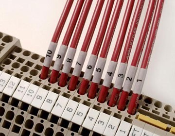
- Choose a wire depending on the application requirements. The selection of wire is dependent on voltage, temperature, and type. Each terminal connection is recommended to accept 16 AWG or two 18 AWG (American Wire Gauge) size wires.
- Splicing of wires should not be done to attain a needed length. Always use a continuous length of wire. Never splice wires to attain a needed length.
- Use the shortest possible wire length.
- Use a good wire management system for routing of wire to minimize the use of wire ties.
- Avoid running control wires near high-energy wiring.
- Avoid running input wiring close to output wiring where possible.
- To minimize voltage drops when wires must run a long distance, consider using multiple wires for the return line.
- Avoid running DC wiring in close proximity to AC wiring where possible.
- Avoid creating sharp bends in the wires.
- Install a powerline filter to reduce power surges and EMI/RFI noise.
Grounding Requirements
Electronic instrumentation such as PLCs and field I/O are typically surrounded by various types of electronic devices and wires. These electronic devices may include power supplies, input/output signals from other instrumentation, and even devices that are near the instrumentation enclosure. All these may present a risk of Electromagnetic Interference (EMI) or transient interference. This type of interference may cause erratic operation of components and cause failures.
In addition to device interference, automation equipment and devices could be damaged by powerful line surges. These line surges may come from common voltage fluctuations from a power supply, lightning, or unintentional contact with a high voltage line. A power surge will cause a temporary failure, fuse burn-up, or could cause serious damage to the equipment. Grounding provides a low impedance path that limits these voltages and stabilizes interference. Grounding is a must to protect your automation equipment and devices from serious damage, failures, and even potential risk to users. Grounding is the foundation of achieving a reliable power distribution system. During the panel and control system build, it is important that a reliable grounding system be implemented. Poor grounding or improper or defective wiring may be the cause of most problems affecting power quality.
- Mounting: refers to the actual physical installation of each device, instrument or component to either the subpanel or other connected equipment.
- Bonding: refers to the joining of metallic parts of a chassis such as; frames, shields, assemblies and enclosures. Joining or bonding these components properly reduce the interference from EMI and ground noise.
- Grounding: refers to a connection to a grounding conductor to provide overload and interference protection.
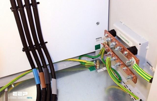
Wire all grounds to the incoming ground lug either directly or with a wire to the other ground bus bars. Add a main ground lug and/or a ground bus bar for each grounded power supply. A number of busbars can be utilized but should all be wired together and then to the incoming ground lug to at least 1 point if not two (2). This is in addition to the ground established through the panel. Use 2 ground wires from opposite ends of the bus or chain of ground bars if the ground is isolated. Wire the ground on all doors and subpanels and the cabinet itself to a ground bar terminated at the main ground lug. Wire all equipment and chassis grounds to the ground bar(s) which is terminated at the main ground lug. For additional details on grounding and bonding see the Grounding and Bonding post dedicated to just this subject.
Use of Shielded Cables
Shielded cables are electrical cables that contain insulating conductors encased in a standard conductive layer. They are used to reduce the interference from electrical noise. Some instrumentation requires the use of shielded cables for specific connections as electromagnetic interference can reduce their performance. When installing instrumentation, it should be verified whether any connection requires a shielded cable. If the product being installed requires shielded cables, the grounding specifications provided by the manufacturer manual must be followed. Failure to use the shielded cable will result in faulty readings or signals from the instrumentation. Improper installation of shielded cables may cause a ground loop that will cause failure on a processor or would allow noise into the logic circuit. The cable must be grounded at one end. This eliminates the potential for noise inducing ground loops. The cable selected should have sufficient shielding for the application's needs. In moderately noisy environments, a foil alone may provide adequate protection. In noisier environments, consider braids or foil-braid combinations. Use an earth ground wherever possible and check the connection between the ground point and the equipment. Eliminating noise depends on a low resistance path to ground therefore it is important to ensure that the equipment the cable is connected is properly grounded.
In part three of this series that will be released next week, we will into more detail about communication testing, startup and commissioning, and also cover maintenance of an automation control system.