A design approach to a PA system encompasses the available technologies and a project-specific project-specific engineered layout. This requires a review of the plan drawings to confirm coverage/functionality and a load calculation of the design circuits thus assuring that the expected sound level is realized at each location.
When reviewing the plan drawings, it is important to understand the differences in performance provided by the different speaker types. The more commonly used speakers are speaker/transformer/baffle assemblies, usually a ceiling mount unit, and the horn speaker type also called a loudspeaker. The horn speaker is normally applied to common areas with high occupancy and outdoor use. Two major differences in performance can be seen in the speakers. Possibly the more important difference is in response rate; the frequency response in the normal speech range is significantly better on the ceiling mount type speaker. This basically means that typical announcements come thru as a more intelligible speech pattern. The other major difference is in the audio output performance. In this, the horn speaker can produce up to 15 watts of audio power while the ceiling mount speaker can produce a maximum of 5 watts. The power rating on the speakers translates directly to sound levels where more power means louder sound.
As noted, the typical mounting of the two-general type of speakers differs. The more common ceiling type speaker is offered in a 2x2 drop-in ceiling tile and also as a pendant back-can configuration for mounting in hard ceilings; either recessed in the ceiling or suspended on a conduit box. The horn speaker is often recessed into a wall but does have a surface mount option. The horn speaker is not easily ceiling mounted.
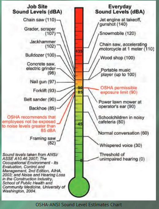
Once the type of speakers in the layout is identified, the sound level has to be established. Because the sound level is directly related to power, louder overall building requirements mean more power must be made available thru the PA system. The typical measurement for sound pressure is the dB scale. The OSHA Sound Level chart is used to establish a baseline with the understanding that the scale is for sustained sound levels and not short announcements.
A typical scale is as follows:
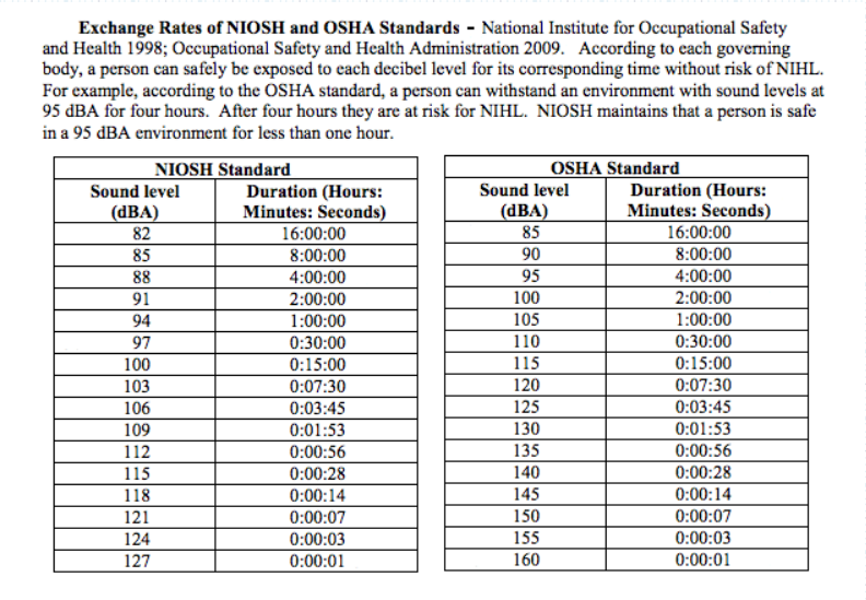
Allowable exposure to the levels are as follows:
From the above, a value of 80 dB is used for a typical classroom, 91 dB for hallways, and 105 dB for horn speakers. After an audible power value is placed on the speakers, a power matrix is created which represents the limits that a PA output card and amplifiers can supply as well as defining the maximum speakers that can be "strung" together…placed in one common circuit. An example of the power matrix is shown below:
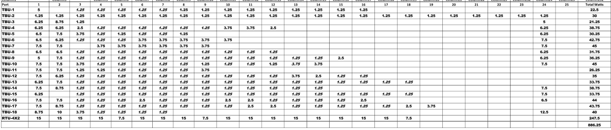
This chart represents a PA system with 18 output cards, each card having 25 output ports and a maximum capacity of 50 watts per card. Note that this system also includes an RTU; a large capacity output module.
Two considerations are accounted for when assigning output ports:
- Maintaining the load per card at below 80%, if possible, but always below 100%. Further evaluation is given to those cards that exceed 80%
- Grouping of PA zones/areas of the building within the same output cards
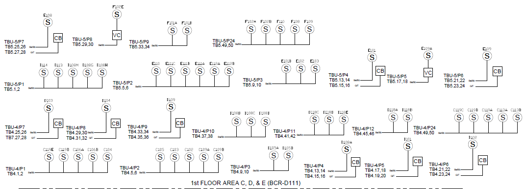
Load assignments to ports are based on the number of speakers in each circuit. This is symbolized by riser diagrams. The riser diagram is a representation of how an output channel will provide power from the port thru each terminal block down to the speaker.
An example is shown below:
Once the power assignments are allocated, the total power (watts) can be calculated, and thus the number of amplifiers required to meet the listed load.
It is important to note that each output port has a maximum capacity. As such, the matrix prevents overloading any one port, the individual card or reaching the limits of assigned amplifiers to respective cards. High loads can be assigned to high output ports and, where needed, space can be made available for future expansion by assigning expected values to the associated ports.
Fieldwork is also simplified as the speaker assignments are engineered to the respective terminal blocks. An example of the expected wiring is shown below.
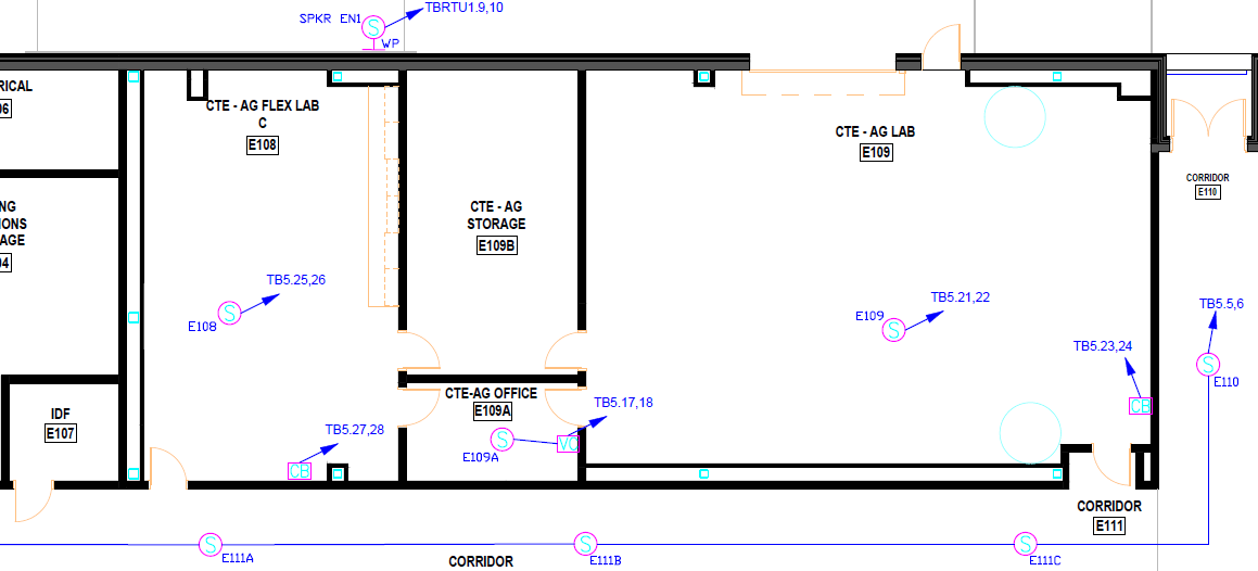
With this approach, field wiring, testing, and troubleshooting can be traced down to specific circuits thus eliminating any guesswork as to where the tie point might be.
The end result is a fully functional system meeting the intended sound levels of each area.